Marine
more Grasshopper Widgets
AC62 Wing Control
Rhino Grasshopper
Controls - 28 June 2014
Scrapped the mysterious graph mapper (which had controls of its own) to implement three "simple" controls to induce twist, independent of camber angle, effectively twisting the top without moving the bottom. Then you can independently change camber (the angle relative to the wing spar of the bottom edge of the bottom flap), making reverse twist possible.
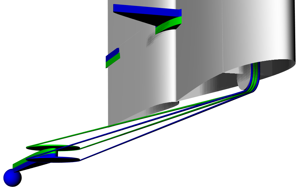
These diagrams show two tillers mounted apart from the wing, probably controlled by lines attached to winches (not shown). They don't need to be tillers, they could be a pair of traveler tracks or any convenient arrangement to act as quadrants, pulling a pair of lines back and forth, up and down through the mast pivot point, as shown.
The blue one (bottom with ball) controls camber - literally the "camber boom" at the bottom of the wing, the bottom edge of the bottom flap.
The green one (top) controls the angle of the top edge of the top flap, relative to the "camber boom" at the bottom. It is the twist control. Three flap joint angles in between top and bottom are split evenly. It can be confusing because unlike the top edge it controls, the angle of the green tiller is always relative to the boat in this scenario. It means that when the green tiller is in the middle, there is no twist, the camber angle will be used all the way to the top.
The third control, wing rotation, is not shown in these diagrams. Any conventional wing tiller arrangement will do.
The three controls work independently of each other.

Fig. 2 - Controls at bottom of wing, top of wing is at bottom left of image.
The blocks at the base of the mast obviously can't be attached to it; they remain fixed relative to the tillers. The control lines are allowed to twist above...
The animation shows only negative angles on camber and mast rotation and only positive on the top flap (green tiller). All three can be either positive or negative angles. Things don't make sense when the difference between camber and top flap exceed ninety degrees.
In practice, it may be preferred to control camber by having lines directly attached to the wing. That still works for this plan, leaving only one control not attached to the wing - the green tiller for the top end of the flaps, the twist control.
External Tiller - 29 June 2014
The two external tillers above are a distraction. One might be handy for twist control but on the AC45 they just use a line hanging on the wing. The effect is the same. Twist is simply an adjustment of control line positions between the "camber boom" and the four flap pivot points above, very much like the AC45.
4 July 2014
The key is having two lines on the "twist quadrant" instead of just one, allowing it to be pulled to either side instead of only to the middle.
- When the twist quadrant is centered (trimmed), there is no twist - the flap angle at the top matches the camber angle at the bottom.
- The twist quadrant is eased to allow twist at the top - relative to the the leading edge, the angle at the top reaches zero, resulting in zero lift.
- Reverse lift at the top is achieved by continuing to rotate the top in the same direction as easing, using force as needed, up to twice the angle of easing to the zero angle/lift position.
Two consequences of the reverse twist capability are:
- need a bigger twist quadrant with at least twice the arc angle.
- need two control lines to control the twist quadrant instead of just one.
I can think of a few ways to use two control lines to rotate the quadrant. (A single hydraulic piston could do the job too!)
The easiest might be to lead two lines to the same place as the one is now, under the bottom flap, but rigged like traveler car controls.
Another would be to lead two lines through the mast pivot to fixed controls (tiller/traveler) that don't rotate with the wing.
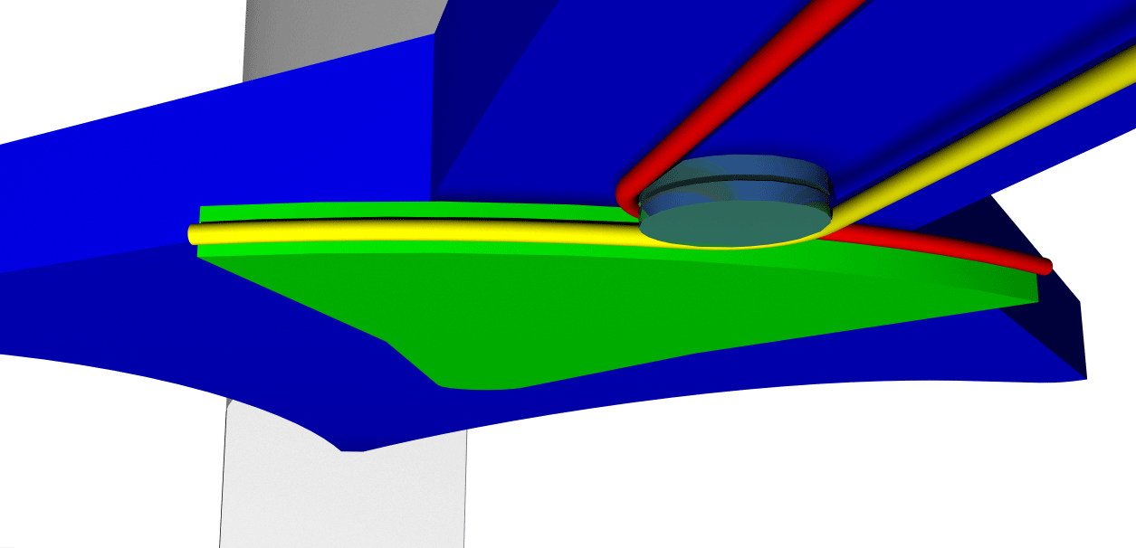
Or the twist quadrant (bright green below) could be extended with an attached tiller, controlled by a pair of sheets, like the mainsheets attached to the trailing edge of the camber boom (bright blue).

Fig. 6 - Two twist control lines, led aft on the camber boom like the AC45, that bring the ends of the quadrant to the center, rotating either direction, a full fifty degrees (+-25)

Fig. 7
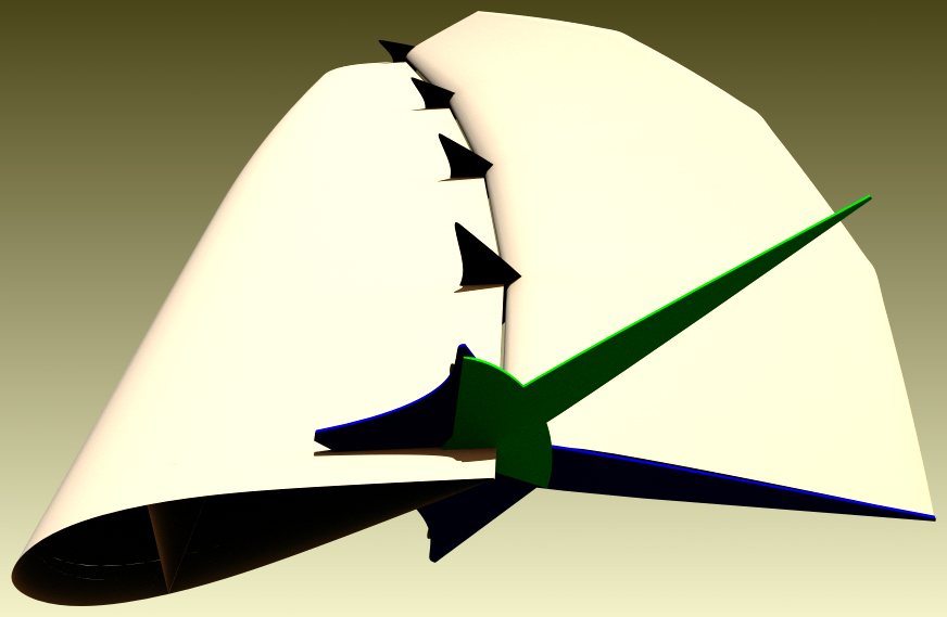
So looking from the top on this animation again, on starboard tack, leading element rotation and camber both locked at twenty degrees:
- Twist quadrant is centered by pulling yellow line.
- Easing yellow line allows top of trailing element to rotate off twenty degrees, in direct line with leading element - zero lift.
- Red line is then pulled to rotate top another twenty degrees, giving negative twenty degrees relative to the leading element, causing reverse lift at top.

Fig. 3
The fifty degree twist quadrant depicted above has a radius of 0.644 meter, it's arc length is 0.562 m (22"). Half of that is the distance that the red and yellow lines must trim and ease, +-0.281 meter (+-11"). Allowing 22" total for trim and ease takes only ~21% of the distance between the turning blocks and the end of the camber boom (2.7 meters, 8.9 feet), leaving the remainder (~79%, 2+ meters, ~7 feet) for the action of multi-part blocks attached to the tail ends of the red and yellow twist control lines.
The two tail ends of the of the multi-part blocks could still be lead through the front element pivot point, where they would be under less tension than if they had not passed through the blocks first...
The 50 degree twist quadrant relies on the 1:2 blocks like the AC45 to turn only half as far as the top of the trailing element. Below, it is being used to 80% of its capacity (20 degrees of 25 max.) on one side only.
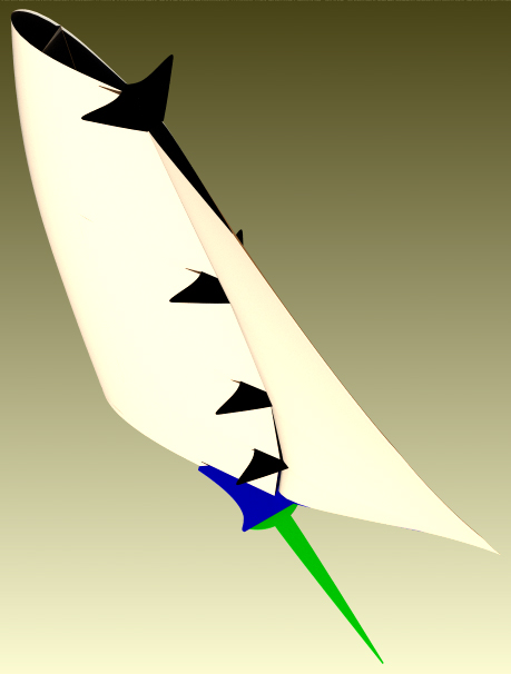
Full tack using reverse twist. Note that from the reverse position ("top flap" dial at 40 degrees), all three controls are then changed at exactly the same rate to keep the top of the trailing element at a fixed angle relative to the lead element during the tack. Because reverse twist effectively tacks the top first, so the lead element and camber boom are just catching up.

Fig. 9 - animated .gif, same as interactive Animation #5
As above, twist tacking the top of the wing first, followed by the bottom - viewed from the top:
- flaps rotate +-40 degrees relative to camber
- camber rotates +-20 degrees relative to forward element
- forward element rotates +-20 degrees relative to boat


