Rudder Replacement on Traditional Schooner
NACA Foils using Rhino Grasshopper, from an SA forum discussion, July, 2016 (ProaSailor)
Images posted to SA threads were lost on the forum when DropBox dropped support for that sort of hosting, so I'm posting my original images here in the context of that thread.

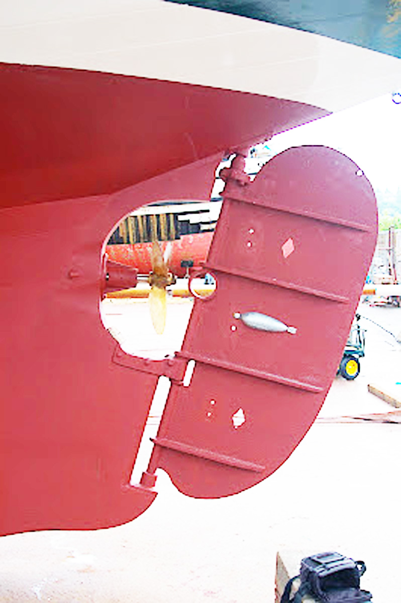
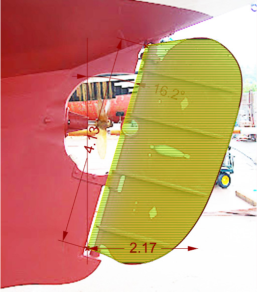
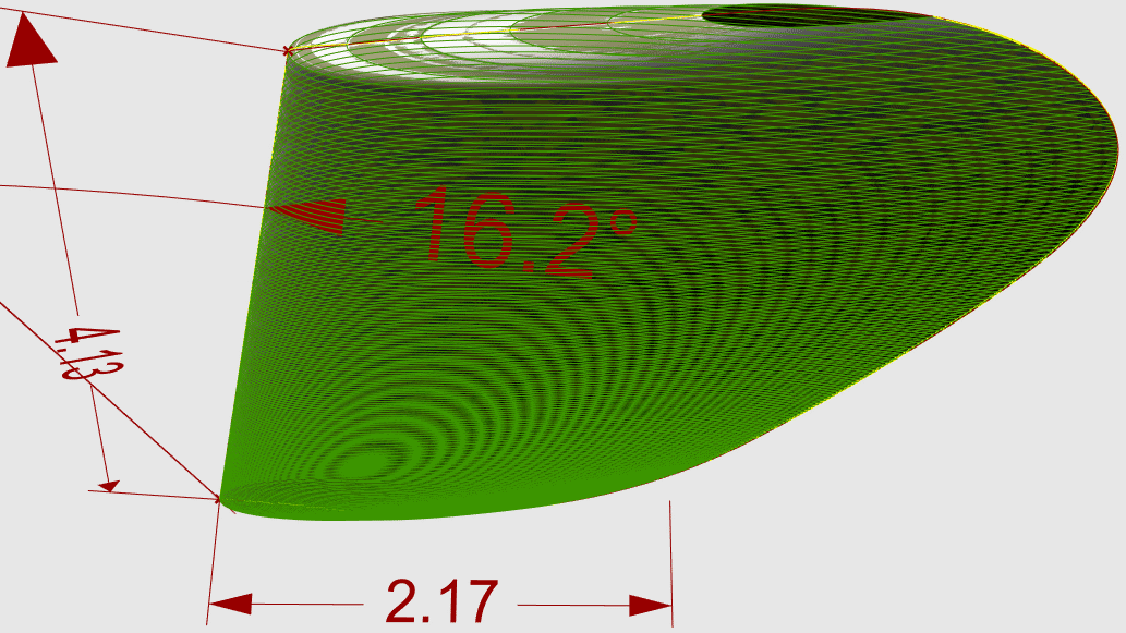
This is a NACA 0012 section, ~12" chord, ~36" tall, extruded or "swept" along a line that is angled sixteen degrees aft at the top (to match the trailing edge of your keel?). A Rhino Grasshopper script so easily scaled to exact dimensions.
Three gudgeon mount points is complicated though, eh? Could drop one or the other of the bottom two gudgeons?
Or drop the keel gudgeons and go with a spade rudder that gives you much more freedom in shape and distance from the prop to work with. Getting a modern, balanced, more effective, vertical axis spade rudder looks possible, depending on cost of top bearings and installation work.
NACA 0012 section:
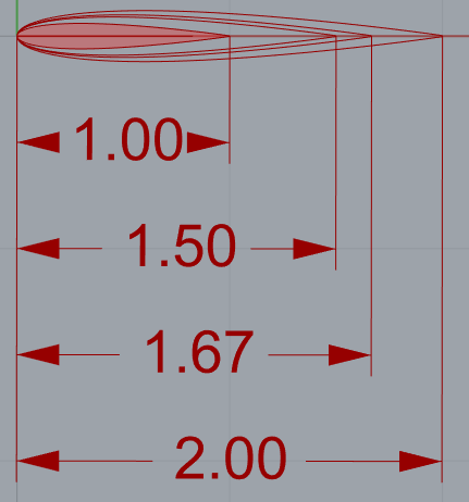
12", 18", 20", 24"...
Give me these three dimensions and I'll give you a CAD file:

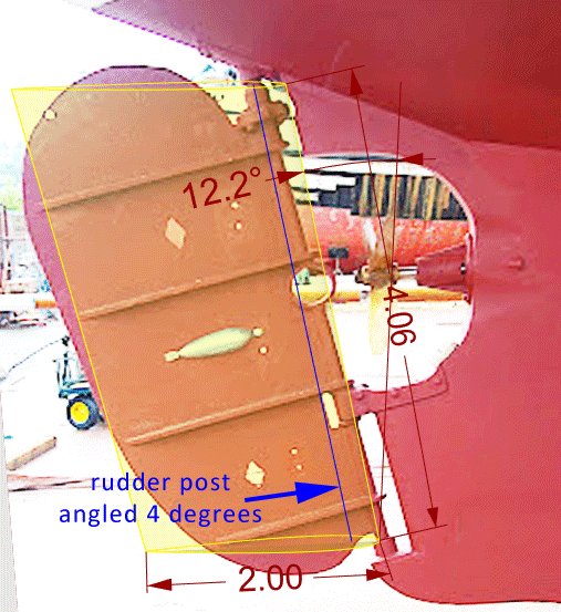
If you drop the bottom gudgeon and extend the second gudgeon aft, the rudder post could be more vertical, better balanced and ventilated, further aft from prop.
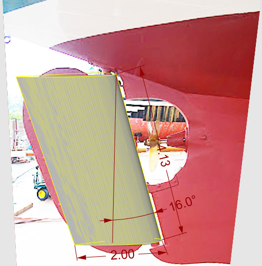
16.2 degrees from vertical? Post length (span) and chord dimensions?
Not to scale, no dimensions from boat...

Vertical option, pivot at ~17% of chord.
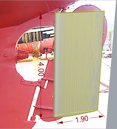

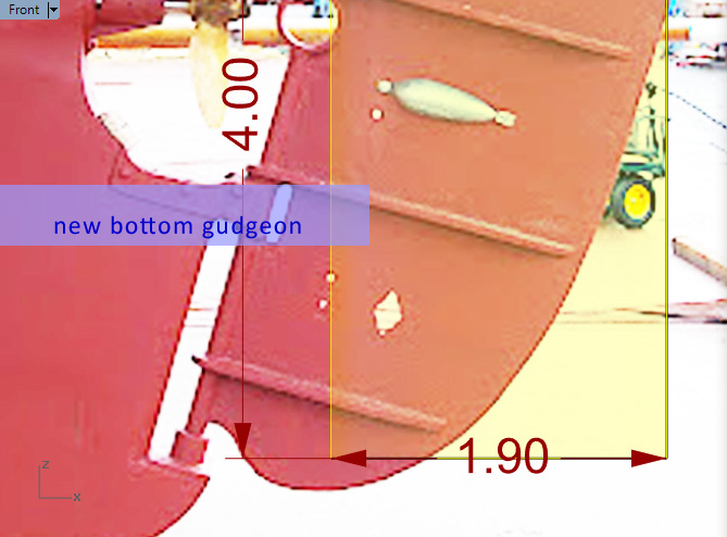
Could be spade style or the second gudgeon could be extended aft by doubling (at least) the length of the current bracket (see light blue "new bottom gudgeon"):
FYI:

If you're going to replace parts and restore existing keel gudgeons, then fairing the rudder surface (horizontal contours) to a NACA foil might be the best you can do. I doubt there is any helm balance from that small triangle.
The only way I see to get a "balanced rudder" is to move to a vertical rudder post, which gives more room for leading edge area between the prop and the rudder shaft.

Two ways of getting a vertical rudder post:
- Extend bottom gudgeon(s) aft. - The engineering and construction of this "strut" is significant!
- Forget about bottom gudgeons/strut and use a spade rudder. - Straightforward parts and solution, rudder profiles are textbook, all deadwood below prop can be carved away at will, perhaps refined over years of haul outs.
P.S. Again, dimensions shown are not to scale for this boat.
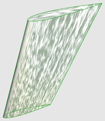
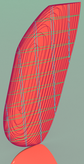
Here is a rudder very close in shape and size to your existing rudder. The horizontal green lines are all scaled NACA 0012 curves, based on length between plane intersection points with the rudder profile curve, lofted to get the surface.

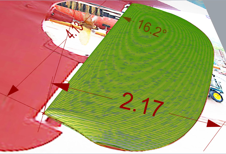

Even if CNC were used, these tip areas with scaled foil profiles aren't doing much of the rudder work, and they are complex to make:
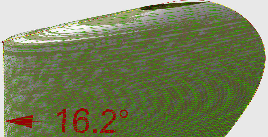
Easier with hand tools to have the constant cross section mentioned earlier (below), horizontal NACA 0012 profile curves, all the same:
Rhino. I've been trying to save .dxf and .dwg files, other formats, but when I import them to SketchUp, the curves aren't smooth anymore.
foil_rudder_2016Jul30a.3dm
Longer chord on green section (below) would make it thicker...

.3ds isn't bad if you don't mind separating the items/layers manually. Even the "PictureFrame" photo survives, for some context.
foil_rudder_2016Jul30a.3ds
Moving either one of the two gudgeons aft ~4" will make room for a balanced rudder, provided a little of the deadwood is carved away.
Still a mess compared to a spade rudder though.
P.S. Getting a "balanced rudder" hydrodynamically WILL NOT solve the issue of balancing the weight of a heavy rudder when the boat is heeled.
What did you end up with for your rudder?


These rudders are coming from an evolved version of the same Rhino Grasshopper tool developed for keel fin shape and root flare in the other thread. Mods:
- apply the "flare" feature to both ends of the fin (tip as well as root)
- support a reduction in chord length (taper) as well as an increase (flare)
- support separate alignments for root and tip by percent chord
Sharpening the pencil! Still perfecting the transitions (tangents) and eliminating surface ripples. Not quite there yet.
Leading edge is on the left for this boat/thread.
It's fun! I've spent a lot more time working to refine the tool/algorithm than actually using it to draw specific shapes, which is why a "real" application like this (SASSAFRASS' boat) is good exercise. I still don't have any dimensions for this boat's rudder or know how much surface area would be ideal or even what the ideal shape is. But the ability to get so many different shapes by making micro adjustments to parameters is very satisfying. MUCH EASIER than redrawing a CAD model "by hand".
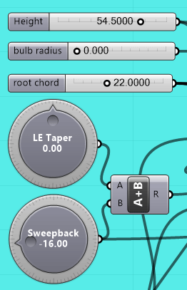


Note that "Sweep Angle" is constant in this case, regardless of "% Chord", because there is no "Leading Edge Taper" ("LE Taper") to the base fin shape. "Sweepback" angle from the knob is applied equally to the leading and trailing edges. By convention, "Sweep" on a foil is typically measured at the 25% chord position. When a foil is tapered, it varies with "% Chord".
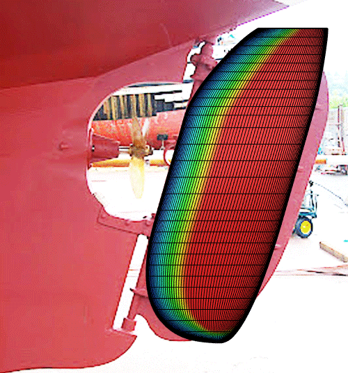
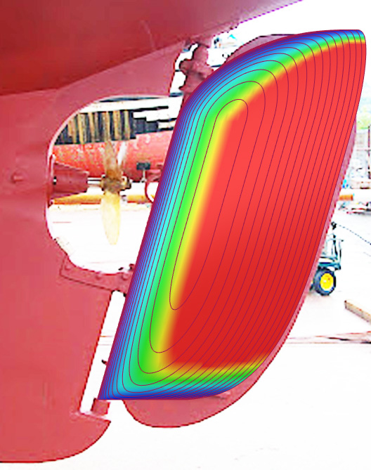
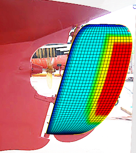
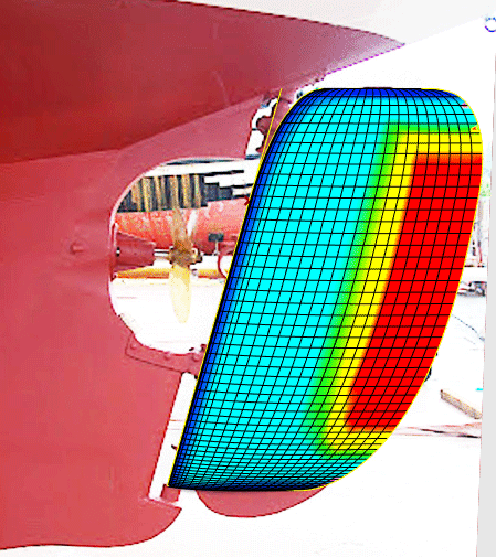
Here's one for you, Brent. A more traditional shape... ;) Still looks funky to me, but it's not because of the tool I'm using. Waste of effort for this boat, perhaps, with its massive keel in the way of clean rudder flow. But it doesn't take long to configure a rudder of any size/shape. Contour lines on the red rendering are at 1/16" intervals:
Hope you can see the animation.

While we're eagerly waiting for the real thing...


Thanks for the update. Looks like you are keeping the same rudder post axis geometry?
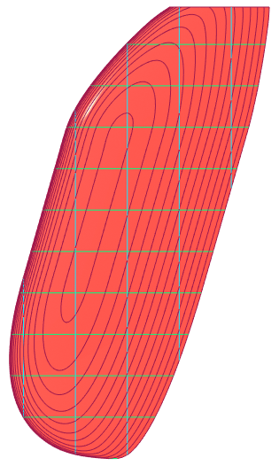
The straight yellow line in this image has 15% of the rudder's cross sectional area forward of it, making the rudder "balanced" if pivoted on that yellow line. One bearing at the top and one at the bottom, skipping the middle gudgeon, a few inches (~4+?) aft of their current locations.
In addition to lighter response at the helm, wouldn't a balanced rudder put less strain on its bearings than one where the fulcrum (pivot axis) is at its leading edge?

The wacky lines on the trailing edge are a curvature graph, the 'CrvGraph' component in Grasshopper. Similar to the previous color images of surface curvature, they are both indicators of fairness, or lack thereof.
"sail the boat unbalanced" meaning sail trim isn't balanced fore and aft with regard to CLR? Putting more load on the rudder, which is hidden by a balanced rudder?
White rudder is pivoting at 15% of area (18% chord on this shape). Blue is pivoting at leading edge and would be shaped accordingly.
Moving the pivot axis aft to a "balance" point causes the leading edge of the rudder to swing out into clear flow on either side.

I sailed with Michael Reppy in S.F. Bay on his 36 (stretched) Shuttleworth trimaran Naia. We were looking to explain and fix a noticeable flutter in the steering at certain speeds. Two balanced spade rudders, widely separated on outboard hulls. At some point we disconnected the steering linkage to one of the rudders and, of course, all was smooth as silk. The disconnected rudder was still easy to control by hand with a short tiller, even at high speed.
Here is a balanced rudder based on moving only the bottom pivot point aft ~8 inches, changing only the angle at the top bearing, skipping the middle gudgeon:
The white rudder, above, is a NACA 0015. This blue one, below, is a NACA 0012:

Strut to be defined/refined... faired.
Both NACA 64-012A, nearly identical. The second one has a longer tip chord.